111-1024x458.png)
Struggling with battery tab or busbar welding?
A practical guide to laser welding from tabs to modules — based on real shop floor experience.
BLOG

CONTACT US
From Tabs to Modules: A Practical Guide to Battery Laser Welding
Battery manufacturing is, at its core, the art of stacking reliable connections. From the tabs inside each cell, to the busbars linking cells together, to the final module connections—every single weld defines the performance and lifespan of the finished product.
JOYLASER has accumulated hands-on manufacturing experience with pouch cells, prismatic cells, and cylindrical cells in the battery welding space. This guide is built on that experience, walking you through the practical process considerations for tab, busbar, and module welding. It’s written for engineers and production technicians who need real-world reference points, not theory.
If you’re a production manager more focused on line speed, yield improvement, and return on investment, there’s a resource at the end of this article specifically for you.
Chapter 1: Three Core Connection Types in Battery Welding
Regardless of cell format—pouch, prismatic, or cylindrical—battery welding needs can be grouped into three categories:
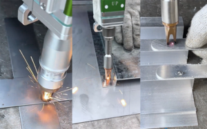
1.1 Tab Welding—The Cell's First Connection
Tabs are the metal strips extending from the positive and negative electrodes inside a cell, connecting it to the external circuit.
| Cell Type | Tab Material | Typical Thickness | Key Requirements |
|---|---|---|---|
| Pouch Cell | Copper-nickel, Aluminum | 0.1-0.3mm | Controlled penetration, no damage to pouch film |
| Prismatic Cell | Aluminum, Copper | 0.2-0.5mm | Strong joint, good conductivity |
| Cylindrical Cell | Copper-nickel | 0.1-0.2mm | Consistent spot placement, accurate positioning |
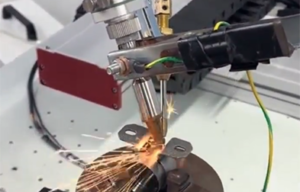
1.2 Busbar Welding—The Bridge Between Cells
Busbars connect multiple cells to form a battery module. Common materials are copper or aluminum, typically 0.5-2mm thick. Key welding requirements include:
Sufficient penetration for current-carrying capacity
Clean weld appearance with minimal spatter
Controlled heat input to avoid damaging cells
1.3 Module Connections—From Module to Pack
Connections between modules, usually copper bars or cabling, share similar requirements with busbar welding but must also account for assembly space and eventual serviceability.
Chapter 2: Tab Welding—Considerations by Cell Type
2.1 Pouch Cell Tab Welding
Pouch cell tabs are thin (0.1-0.3mm) and sit directly against the aluminum laminate film. Key considerations:
Heat input control: Use pulsed welding to minimize heat-affected zone spread
Backing support: Ensure the tab is backed by a rigid surface to prevent burn-through
Weld count: Depending on design, typically 2-4 spots to ensure conductivity
Common issues: Burn-through damaging the pouch film, or cold welds causing high internal resistance. These can be managed through parameter tuning and proper fixturing.
2.2 Prismatic Cell Tab Welding
Prismatic cell tabs are thicker (0.2-0.5mm), with aluminum being common. Key points:
Cleanliness: Tabs must be free of oxidation and oil
Welding approach: Continuous pulse or galvanometer multi-spot welding
Weld appearance: Smooth surface, no cracks
2.3 Cylindrical Cell Tab Welding
Cylindrical cell tabs are typically copper-nickel. Considerations:
Plating: Nickel plating helps with laser absorption, but excessive thickness may affect conductivity
Spot placement: Must land precisely where the tab contacts the cell cap
Strength: Must meet pull test requirements
Chapter 3: Busbar Welding—The Core of Module Assembly
3.1 Materials and Thickness
Busbars are commonly copper or aluminum, typically 0.5-2mm thick. Different materials respond differently to laser energy:
Copper: Lower absorption of infrared laser energy; requires higher power density
Aluminum: Better absorption but affected by surface oxidation
3.2 Welding Approach by Application
| Busbar Type | Common Approach | Notes |
|---|---|---|
| Thin copper (0.5-1mm) | Pulsed spot welding | Controlled heat input, minimal distortion |
| Thick copper (1-2mm) | Continuous scanning | Sufficient penetration, good efficiency |
| Aluminum | Pulsed or galvanometer | Must penetrate oxide layer |
Note: These are general references. Actual parameters should be determined through testing with your specific materials.
3.3 Common Issues and Troubleshooting
| Issue | Possible Causes | General Approach |
|---|---|---|
| Insufficient penetration | Low power, high speed | Increase power, reduce speed |
| Excessive spatter | High energy density, contamination | Adjust pulse shape, clean surface |
| Poor weld appearance | Parameter instability, loose fixturing | Check equipment, secure fixturing |
Note: These are general troubleshooting guidelines. Solutions should be validated with your specific materials and equipment.
Chapter 4: Module Connections—From Cells to Pack
Once modules are assembled, they must be connected into a complete battery pack. This stage has its own characteristics:
Limited access: Modules are packed tightly; the weld head must reach confined spaces
Thicker materials: Interconnect bars can be 2-3mm thick
Serviceability: Some connections may need to accommodate future disassembly
4.1 Common Welding Approaches
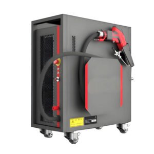
Handheld laser welding: Flexible, good for tight spaces
Desktop welding: Stable, suitable for regularly arranged modules
Galvanometer welding: Efficient for high-volume multi-spot applications
4.2 Process Validation
After module connection welding, typical checks include:
Visual inspection: Continuous seams, no cracks
Pull testing: Adequate joint strength
Resistance measurement: Within design specifications
Chapter 5: Frequently Asked Questions
Q1: Pouch cell tabs are easy to burn through. How do you control this?
A: Pouch cell tabs are thin (0.1-0.3mm) and sit directly against the pouch film. The recommended approach is pulsed welding with controlled energy per pulse, plus a rigid backing under the tab. Sample testing helps determine the right pulse width and peak power for your specific materials.
Q2: What power is needed for copper busbars?
A: Copper has lower absorption of infrared laser energy, so higher power density is typically required. Based on general experience, 0.5-1mm copper busbars can be tested with 1500W pulsed lasers; 1-2mm busbars may require 2000W+ continuous wave lasers. The right choice depends on material composition, surface condition, and weld requirements—confirmed through sample testing.
Q3: What tests should be done after battery welding?
A: Common tests include: visual inspection (weld appearance, spatter), pull testing (joint strength), resistance measurement (connection quality), and cross-section analysis (penetration depth, heat-affected zone). Depending on the application, additional reliability tests (vibration, thermal cycling) may be required.
Q4: What battery types can your equipment handle?
A: JOYLASER laser welders have been used for pouch cell tab welding, prismatic cell busbar welding, cylindrical cell tab welding, and battery module connections. Specific parameters depend on your materials, thicknesses, and design—determined through sample testing.
Q5: How can we validate your process for our specific battery?
A: We recommend sample testing. You provide cell tabs, busbars, or module samples; our applications engineers run welding tests based on your requirements and deliver samples, parameter recommendations, and test reports.
Summary: Find the Right Process Through Practical Experience
There’s no one-size-fits-all parameter set for battery welding. Different materials, thicknesses, and geometries all require tailored process development. JOYLASER’s hands-on experience with pouch, prismatic, and cylindrical cells provides a practical foundation for your battery manufacturing challenges.
If you’re an engineer seeking process support, contact us to discuss sample testing.
For Production Managers: If your focus is on line speed, yield improvement, and ROI, we’ve prepared a Battery Laser Welding ROI Analysis Report. It includes payback period modeling, real-world case data, and guidance on evaluating how welding affects overall production line efficiency. Contact us for a copy.